


RADAR Capabilities With 2.92mm LiteTouch Connectors

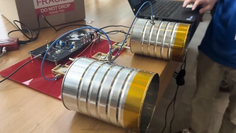
Alongside PCB connector simulations and connector performance analysis, work at SV Microwave as an electrical engineer can also include various passion projects. My latest project, SARizard, sought to construct a RADAR system using SV Microwave components. While I initially used the MIT RES.LL-003 online course, the materials selected for that RADAR seemed outdated, and unreliable. With this project, I updated the course materials, sourced new components off of SV Microwave’s COTS product list, and worked with our distributors to create a functional RADAR.
2.92mm LiteTouch Connectors
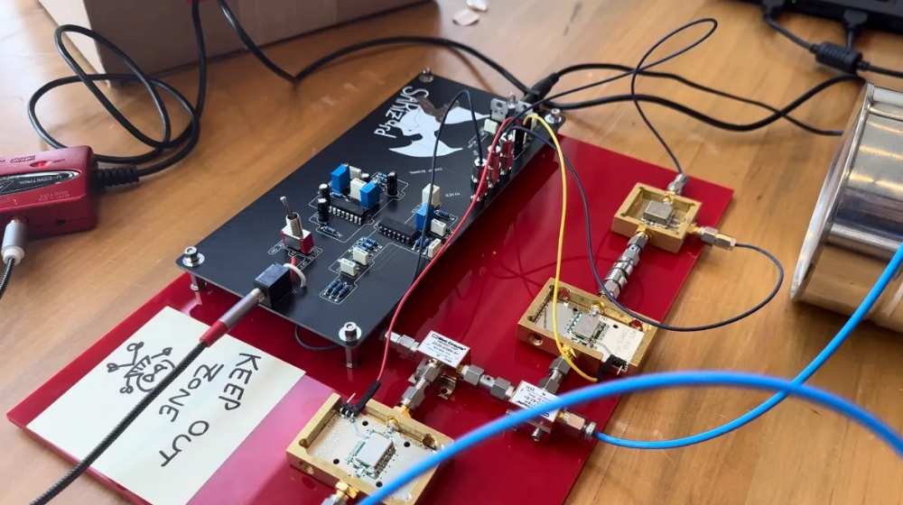
To improve reliability in the RADAR, I selected 2.92mm LiteTouch connectors. The LiteTouch connectors were ideal for several reasons:
- The LiteTouch interface, with its retractable, pogo-pin-style, center contact design allowed me to quickly test each PCB without causing any damage to the PCB trace.
- The solderless design of the connector meant that it was quick and easy to install. I did not need to recruit a solder technician to help me affix these parts onto the board.
- The radar was only operating at a maximum frequency of 2.5GHz, but the 2.92 interface was readily available and can mate to 3.5mm and SMA interfaces.
I knew from some of my electrical simulations that a 2.92mm LiteTouch connector could be trusted to provide good, reliable performance at 2.5GHz. In fact, LiteTouch is rated through 40GHz. Because of this, the LiteTouch connector would not require any optimization, though if it had, I could have simply used SV’s readily-available HFSS and CST electrical models.
Now that I had my PCB connectors selected, I began working with distributors to source the various other parts that I would need for my PCB:
1. DigiKey was able to provide the necessary PCB components.
2. Mini-Circuits provided the active RF modules as recommended by the course lectures and design files.
3. JLC PCB allowed me to quickly have prototype and final revision PCBs made at an affordable price and short lead time.
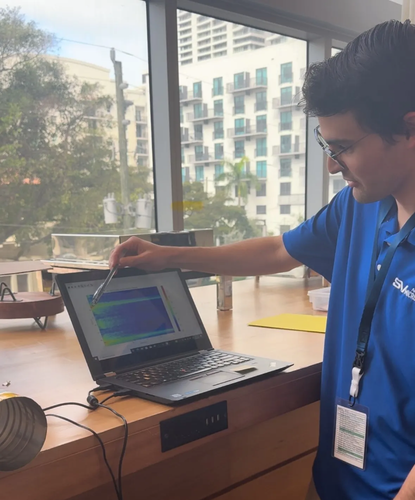
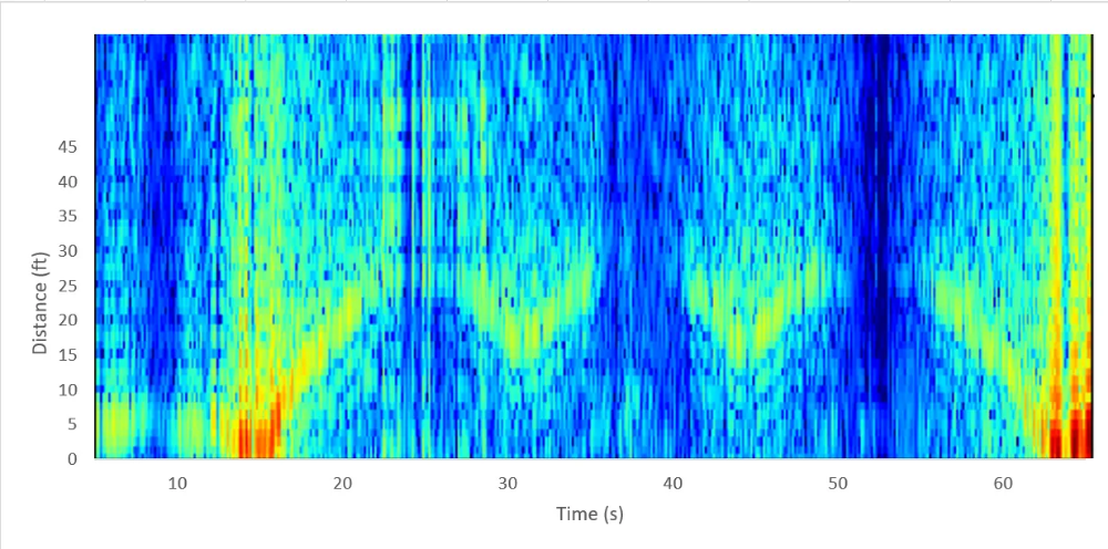
We debuted SARizard at our annual Sales & Marketing Meeting. The RADAR worked perfectly, tracking a moving object through an empty room and providing both readouts on time and distance away from the RADAR. In the future, an impedance-controlled PCB would provide better results. My design did not use 50Ω traces, which would help reduce power loss and improve signal integrity in the final results. However, impedance-controlled PCBs are more expensive and I felt that my decision to go from breadboard to PCB was already a large enough improvement over the original MIT design.
recent releases
RADAR Capabilities With 2.92mm LiteTouch Connectors
Alongside PCB connector simulations and connector performance analysis, work at SV Microwave as an electrical engineer can also include various passion projects. My latest project, SARizard, sought to construct a RADAR system using SV Microwave components. While I initially used the MIT RES.LL-003 online course, the materials selected for that RADAR seemed outdated, and unreliable. With this project, I updated the course materials, sourced new components off of SV Microwave’s COTS product list, and worked with our distributors to create a functional RADAR.
2.92mm LiteTouch Connectors
To improve reliability in the RADAR, I selected 2.92mm LiteTouch connectors. The LiteTouch connectors were ideal for several reasons:
- The LiteTouch interface, with its retractable, pogo-pin-style, center contact design allowed me to quickly test each PCB without causing any damage to the PCB trace.
- The solderless design of the connector meant that it was quick and easy to install. I did not need to recruit a solder technician to help me affix these parts onto the board.
- The radar was only operating at a maximum frequency of 2.5GHz, but the 2.92 interface was readily available and can mate to 3.5mm and SMA interfaces.
I knew from some of my electrical simulations that a 2.92mm LiteTouch connector could be trusted to provide good, reliable performance at 2.5GHz. In fact, LiteTouch is rated through 40GHz. Because of this, the LiteTouch connector would not require any optimization, though if it had, I could have simply used SV’s readily-available HFSS and CST electrical models.
Now that I had my PCB connectors selected, I began working with distributors to source the various other parts that I would need for my PCB:
1. DigiKey was able to provide the necessary PCB components.
2. Mini-Circuits provided the active RF modules as recommended by the course lectures and design files.
3. JLC PCB allowed me to quickly have prototype and final revision PCBs made at an affordable price and short lead time.
We debuted SARizard at our annual Sales & Marketing Meeting. The RADAR worked perfectly, tracking a moving object through an empty room and providing both readouts on time and distance away from the RADAR. In the future, an impedance-controlled PCB would provide better results. My design did not use 50Ω traces, which would help reduce power loss and improve signal integrity in the final results. However, impedance-controlled PCBs are more expensive and I felt that my decision to go from breadboard to PCB was already a large enough improvement over the original MIT design.