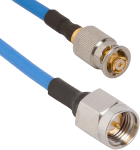
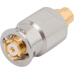
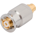
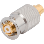
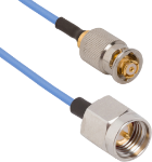
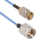
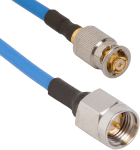
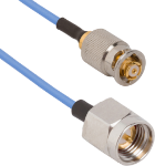
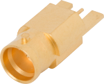
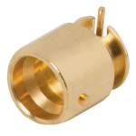
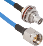
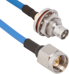
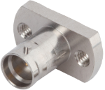
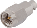
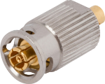
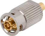
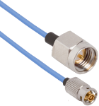
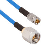
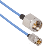
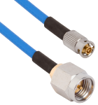
Secure Locking SMP/SMPM RF Cable Assemblies
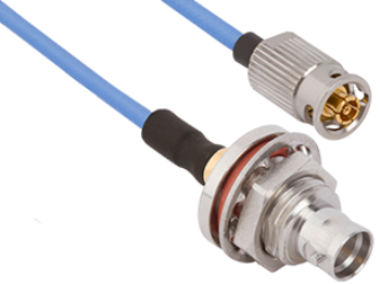
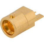
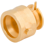
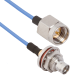
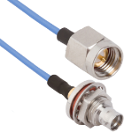
SV Microwave's secure locking QuarterBack® RF cable assemblies utilize a quarter turn bayonet style coupling nut with a locking feature for standard SMP / SMPM interfaces and standard female and male bulkhead SMPM interfaces. All SV QuarterBack® products are ideal for high vibration and test applications that require a large number of mating cycles.
Features / Benefits:
- Quarter turn bayonet locking feature on standard SMPM interface
- Low VSWR through 40 GHz (SMP) /65 GHz (SMPM and SMPS)
- Female cable connector options available for all flexible cable types .086” diameter and smaller
- Low insertion/extraction forces, compared to standard full detent SMP and SMPM, means less torque on board mount connector solder joints during mating and demating
- Spring loaded positive mating feature allows excellent electrical performance even in extreme vibration environments
- Low mating forces allow for more mating cycles without failure compared to full detent SMP and SMPM
- Available in SMP, SMPM and SMPS
Applications
- Bench-top testing (PCB mount, cable connectors and adapters)
- High vibration environments
- Applications requiring a high number of mating cycles
- Military and Commercial options available
2.92 mm
| Impedance (Ω) | 50 |
| Frequency GHz | 40 GHz |
| Shielding Effectiveness | ≥ -100 dB |
| Dielectric withstanding Voltage | 750 VRMS |
| Mating Cycles | 500 |
| Mating Torque | 7 - 10 in - lbs |
| Inter-mate ability | SMA |
| Temperature Rating | -65°C to +165°C |
| Corrosion (salt spray) | MIL-STD-202, Method 101, Condition B |
| Vibration | MIL-STD-202, Method 204, Condition D |
| Shock | MIL-STD-202, Method 213, Condition I |
| Thermal Shock | MIL-STD-202, Method 107, Condition B |
| Moisture Resistance | MIL-STD-202, Method 106, Less Step 7B |
| Barometric Pressure (Altitude) | MIL-STD-202, Method 105, Condition C, 70k Ft. |
SMA
| Impedance (Ω) | 50 |
| Frequency GHz | 18 GHz (select models to 26.5 GHz) |
| Shielding Effectiveness | ≥ -90 dB |
| Dielectric withstanding Voltage | 1000 VRMS |
| Mating Cycles | 500 |
| Mating Torque | 7 - 10 in - lbs |
| Inter-mate ability | 2.92mm |
| Temperature Rating | -65°C to +165°C |
| Corrosion (salt spray) | MIL-STD-202, Method 101, Condition B |
| Vibration | MIL-STD-202, Method 204, Condition D |
| Shock | MIL-STD-202, Method 213, Condition I |
| Thermal Shock | MIL-STD-202, Method 107, Condition B |
| Moisture Resistance | MIL-STD-202, Method 106, Less Step 7B |
| Barometric Pressure (Altitude) | MIL-STD-202, Method 105, Condition C, 70k Ft. |
SMP
| Impedance (Ω) | 50 |
| Frequency GHz | 40 GHz |
| Shielding Effectiveness | ≥ -80 dB DC - 3 GHz ≥ -65 dB 3 - 26.5 GHz |
| Dielectric withstanding Voltage | 500 VRMS |
| Mating Cycles - SB | 1000 |
| Mating Cycles - LD | 500 |
| Mating Cycles - FD | 100 |
| Insertion Force - SB | 3.0 lbs |
| Insertion Force - LD | 5.0 lbs |
| Insertion Force - FD | 7.0 lbs |
| Withdrawal Force - SB | 0.5 lbs |
| Withdrawal Force - LD | 7.0 lbs |
| Withdrawal Force - FD | 9.0 lbs |
| Axial Misalignment | .010” Max |
| Radial Misalignment | 3° Max |
| Temperature Rating | -65°C to +165°C |
| Corrosion (salt spray) | MIL-STD-202, Method 101, Condition B |
| Vibration | MIL-STD-202, Method 204, Condition D |
| Shock | MIL-STD-202, Method 213, Condition I |
| Thermal Shock | MIL-STD-202, Method 107, Condition B |
| Moisture Resistance | MIL-STD-202, Method 106, Less Step 7B |
| Barometric Pressure (Altitude) | MIL-STD-202, Method 105, Condition C, 70k Ft. |
SMPM
| Impedance (Ω) | 50 |
| Frequency GHz | 65 GHz |
| Shielding Effectiveness | ≥ -80 dB DC - 3 GHz ≥ -65 dB 3 - 26.5 GHz |
| Dielectric withstanding Voltage | 325 VRMS |
| Mating Cycles - SB | 500 |
| Mating Cycles - FD | 100 |
| Insertion Force - SB | 2.5 lbs |
| Insertion Force - FD | 4.5 lbs |
| Withdrawal Force - SB | 1.5 lbs |
| Withdrawal Force - FD | 6.5 lbs |
| Axial Misalignment | .010” Max |
| Radial Misalignment | 3° Max |
| Temperature Rating | -65°C to +165°C |
| Corrosion (salt spray) | MIL-STD-202, Method 101, Condition B |
| Vibration | MIL-STD-202, Method 204, Condition D |
| Shock | MIL-STD-202, Method 213, Condition I |
| Thermal Shock | MIL-STD-202, Method 107, Condition B |
| Moisture Resistance | MIL-STD-202, Method 106, Less Step 7B |
| Barometric Pressure (Altitude) | MIL-STD-202, Method 105, Condition C, 70k Ft. |
SF1112-6144
2.92mm Adapters SF1112-6144
SF1132-6078
2.92mm Adapters SF1132-6078
7012-1084
SMP Cable Assemblies 7012-1084
7012-1085
SMP Cable Assemblies 7012-1085
1221-40051
SMP Connectors 1221-40051
1221-40049
SMP Connectors 1221-40049
1221-40050
SMP Connectors 1221-40050
7012-1302
SMP Cable Assemblies 7012-1302
7012-1303
SMP Cable Assemblies 7012-1303
7012-1300
SMP Cable Assemblies 7012-1300
7012-1301
SMA Cable Assemblies 7012-1301
1211-66195
SMP Connectors 1211-66195
1211-40032
SMP Connectors 1211-40032
Part # 7012-1087
SMP Male QB Bulkhead to SMA Male 12" Cable Assembly for .085 Cable
Available Inventory: 3
7012-1087
SMP Cable Assemblies 7012-1087
Part # 7012-1086
SMP Male QB Bulkhead to SMA Male 6" Cable Assembly for .085 Cable
Available Inventory: 45
7012-1086
SMP Cable Assemblies 7012-1086
Part # SF1211-66214
SMP Male QB Solderless PCB Compression Mount Connector, 2 Hole (Stripline)
Available Inventory: 126
SF1211-66214
SMP Connectors SF1211-66214
1112-6114
SMP Adapters 1112-6114
3221-60003
SMPM Connectors 3221-60003
3221-60004
SMPM Connectors 3221-60004
7032-8547
SMPM Cable Assemblies 7032-8547
7032-8544
SMPM Cable Assemblies 7032-8544
7032-8548
SMPM Cable Assemblies 7032-8548
7032-8545
SMPM Cable Assemblies 7032-8545
3211-60118
SMPM Connectors 3211-60118
3211-60112
SMPM Connectors 3211-60112
Part # 7032-9469
SMPM Male QB Bulkhead to SMA Male 12" Cable Assembly for .047 Cable
Available Inventory: 83
7032-9469
SMPM Cable Assemblies 7032-9468
Part # 7032-9468
SMPM Male QB Bulkhead to SMA Male 6" Cable Assembly for .047 Cable
Available Inventory: 62
7032-9468
SMPM Cable Assemblies 7032-9468


