


What is the difference between return loss and VSWR?
For many engineers, there is no functional difference between return loss and VSWR (Voltage Standing Wave Ratio); after all, they are measurements of the same parameter. They both measure the amount of RF signal transmitted by a connector that is reflected back. So what separates the two?
What's the Difference Between Return Loss and VSWR?
Return loss (See Figure 1) is a logarithmic measurement of RF signal that is more useful when displaying very small reflections. Generally, return loss is used when system designers are working with other elements that are also expressed in return loss.
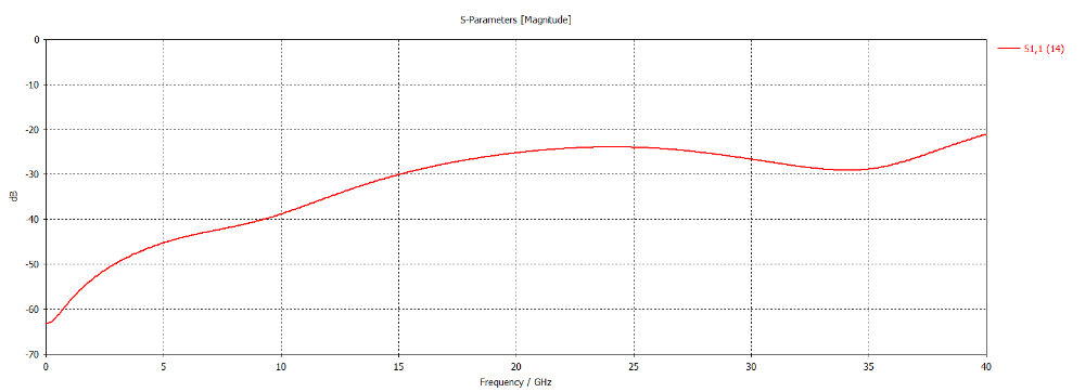
Figure 1: Return Loss Plot
VSWR (See Figure 2) is a more common industry standard. Its intuitive measurement of RF signal is easily expressed visually. This is because VSWR is calculated through a ratio that determines the maximum to minimum voltage in a standing wave pattern and always has a positive correlation.
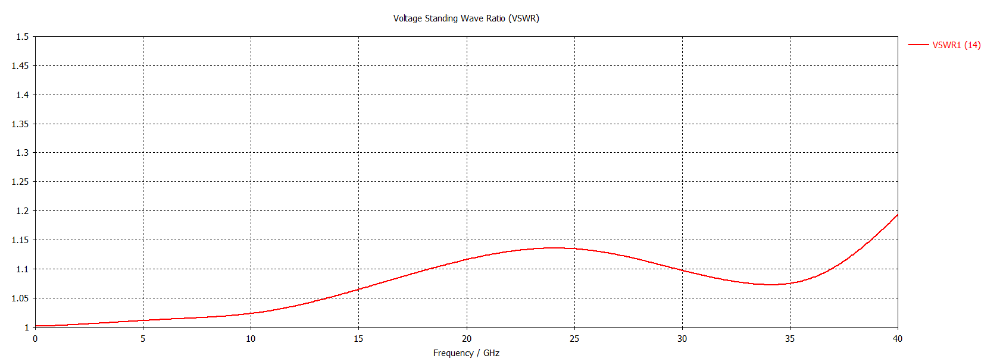
Figure 2: VSWR Plot
SV Microwave's Return Loss and VSWR Test
At SV Microwave, we test how much RF signal is reflected back in each interconnect. This is important to our customers because it is an instant measure of performance. A connector with a high return loss degrades signal integrity and can potentially damage various transmitting elements within a designed system. Generally, all SV connectors and cable assemblies have a VSWR of 1.2:1 or a return loss of -20dB.
As the signal frequency increases, achieving a low VSWR or Return Loss becomes more difficult. This is because the signal wavelength decreases and is more likely to reflect off an imperfection in the coaxial transmission structure. Imperfections are typically a result of machining and assembly tolerances in press fit parts. Often SV’s products have a tiered VSWR specification where the VSWR requirement at low frequency (18 GHz or lower) is tighter than at higher frequencies (18 GHz+).
There are several ways that we ensure this standard. SV Microwave has invested in several different simulation software programs like HFSS and CST. Now, our electrical engineers can simulate and optimize the RF signal of a connector before production ever begins. With HFSS and CST, we bypass prototyping, decrease lead-time for custom designs, and increase the quality of our products, all before the metal is ever cut.
recent releases
What is the difference between return loss and VSWR?
For many engineers, there is no functional difference between return loss and VSWR (Voltage Standing Wave Ratio); after all, they are measurements of the same parameter. They both measure the amount of RF signal transmitted by a connector that is reflected back. So what separates the two?
What's the Difference Between Return Loss and VSWR?
Return loss (See Figure 1) is a logarithmic measurement of RF signal that is more useful when displaying very small reflections. Generally, return loss is used when system designers are working with other elements that are also expressed in return loss.
Figure 1: Return Loss Plot
VSWR (See Figure 2) is a more common industry standard. Its intuitive measurement of RF signal is easily expressed visually. This is because VSWR is calculated through a ratio that determines the maximum to minimum voltage in a standing wave pattern and always has a positive correlation.
Figure 2: VSWR Plot
SV Microwave's Return Loss and VSWR Test
At SV Microwave, we test how much RF signal is reflected back in each interconnect. This is important to our customers because it is an instant measure of performance. A connector with a high return loss degrades signal integrity and can potentially damage various transmitting elements within a designed system. Generally, all SV connectors and cable assemblies have a VSWR of 1.2:1 or a return loss of -20dB.
As the signal frequency increases, achieving a low VSWR or Return Loss becomes more difficult. This is because the signal wavelength decreases and is more likely to reflect off an imperfection in the coaxial transmission structure. Imperfections are typically a result of machining and assembly tolerances in press fit parts. Often SV’s products have a tiered VSWR specification where the VSWR requirement at low frequency (18 GHz or lower) is tighter than at higher frequencies (18 GHz+).
There are several ways that we ensure this standard. SV Microwave has invested in several different simulation software programs like HFSS and CST. Now, our electrical engineers can simulate and optimize the RF signal of a connector before production ever begins. With HFSS and CST, we bypass prototyping, decrease lead-time for custom designs, and increase the quality of our products, all before the metal is ever cut.
how is this calculated??
I thought a 1.2:1 VSWR would yield a 10.4dB return loss.
or am I using a non-std formula (RL=−20log10(sqrt((VSWR+1)/VSWR−1)))
Hi Archie,
1.2 VSWR is approximately 20 dB.
We are unsure if your formula was incorrect or performed incorrectly. However, there are many online calculators that can help with this conversion.